The Mercury Marine 470 (224 CI in-line 4 cyl) was first introduced in 1976.
It was a powerful (170hp) 4 cylinder which was a popular alternative to the
old 160 and 165 in-line 6 cylinder.
The 470 uses an aluminum block which was designed and manufactured
by Mercury Marine. The iron head was from a Ford 460 V8 engine.
The 470 block was also used in the 170, 165 (3.7 Liter),
485 (4 barrel), 488 (4 barrel), 190 (4 barrel), and the 180 (3.7LX with 4 barrel).
All of the 470 and 3.7L versions used closed cooling systems.
The aluminum circulation pump impellar was located on the front end of the camshaft.
This required a way to separate the cooling system from the engines crankcase area.
The cam passes through two seals, which are press fit into the timing chain cover.
The Problem
With time, the front seals will wear on the cam. A groove will form on the cam
and the seals will start to leak. Coolant will usually leak past only the 1st front seal
and then run down a coolant leak passage at the bottom of the timing cover.
Owners will see coolant leaking from the bottom of the front of the engine.
Do NOT plug this passage! The passage is made to vent off the leaked coolant
in an effort to prevent coolant from leaking past the 2nd seal and into the engines oil.
Once coolant is found to be leaking from this passage it is an indication to the owner
that he is to have the engine serviced before the 2nd seal fails and allows coolant to
contaminate the engines oil and possibly cause overheating as a result of lack
of coolant left in the closed cooling system.
The Repair
This can be a difficult and time consuming repair.
Only experienced or very mechanically inclined individuals should attempt this repair.
It will require 2 special tools.
1. A puller kit to remove the Rotor/Damper (Snap-On Gear Puller Kit or other puller set)
2. A Rotor installation tool (Mercury 91-93656A 1 for about $144.75)
You will also need a way to press out the old seals and a way to carefully
press the new seals into place without warping or cracking the timing cover.
It is best to remove the engine and the oil pan to complete this repair.
Sometimes the repair can be completed without the removal of the engine
but the oil pan gasket may get damaged and leak oil.
You must have enough room in front of the engine to remove and reinstall the
rotor/damper. The installer tool is about 10" long so check to see it will fit.
If you do not have enough room for the tools to remove and install the rotor
then you will have to remove the engine to complete this repair.
In-The-Boat Method Disassembly
Now that you are sure you can remove and install the rotor from the front
of the crankshaft you can begin.
Disconnect the battery ground and then the battery positive leads.
Drain all the coolant from the engine by removing the brass drain plug
from the bottom of the timing chain cover. Also disconnect the coolant hose
from the front of the engine.
Remove the lag bolts that are bolting the front mount to the floor.
Use a hoist and gently lift the engine from the front lifting ring just
enough to take the weight off of the front mount.
For safety, place a couple of wood blocks under the engine to prevent
it from dropping should the hoist break free.
Now remove the bolts that attach the front mount assembly to the engine and
get the entire front mount assembly out of the way.
The rotor is held onto the crank with a bolt. Remove the bolt.
(it is a standard bolt, turn left to remove)
Install your puller (using three adequate bolts) and remove the rotor from the crank.
Note: The rotor has a series of magnets glued in place. Be careful not to drop,
bang or hammer the rotor as the magnets will come free or break. Also be careful
that magnetic tools, bolts, etc don't get stuck on the magnets before installation or damage
may occur to your stator windings.
On the port side of the engine block you will find the water cooled voltage regulator/rectifier.
Remove the two yellow/red stripe stator wires from the regulator/rectifier. Look how the wires
lead to the stator. You will see a wire retainer near the timing chain cover that holds the
wires in place. Make note of the retainers position and remove the retainer.
Now take the correct size allan wrench and remove the 5 stator retainer screws and remove the stator.
Remove the 3 screws which hold the triangular hose connector to the front cover.
There are APPROXIMATELY 5 screws going up though the oil pan into the front timing cover
which will have to be removed. The oil pan gasket will be sealing up against the bottom
of the timing cover housing. More on this later.
Remove the 10 screws from the front water pump cover plate and remove the plate.
You will now have full access to the aluminum circulating pump impellar.
The impellar is held onto the front end of the camshaft in one of three ways.
Early 470 models used a nut and lock-washer method.
The nose of the cam was actually machined with a threaded section on the end.
Later models used a bolt and lock-washer which screwed into a threaded hole
in the front of the cam.
More recent models had a "nut-shape" cast into the impellar and the entire
impellar threaded onto the end of the camshaft (spins to right to remove).
Use caution with open flames to prevent damage, injury or death .
Do not use open flames near gas lines or if any gas fumes are present.
Use a very small torch or heat lamp to gently warm the center of the impellar to soften
any Loc-tight that may have been applied during assembly at the factory.
Observe the correct thread direction (depending on which fastener method was used)
and remove the impellar from the camshaft.
Double check to make sure you have removed all the bolts going up though the oil pan
flange into the front cover. If you accidentally leave any of those bolts in place you will
damage the oil pan and timing cover if forced loose.
Remove all of the bolts holding the cover to the front of the engine.
The block will have two locating dowl pins going through and into the timing cover.
This means that the cover will have to be nudged straight forward to be removed but
you will destroy the oil pan gasket when doing so.
To prevent the cork oil pan gasket from ripping during the removal of the timing cover
you will need to use a thin razor knife or a single edged razor blade to release
the gasket from the cover.
Work the blade between the cork gasket and the bottom of the timing cover for the
entire width of the front timing cover.
This is very difficult to do and it will take some effort and time.
Remember, if you ruin the oil pan gasket you will need to remove the engine and its
oil pan to install a new gasket.
Now that you have completely separated the gasket from the bottom of the timing cover
you can gently and slowly start to pry the timing cover forward.
Nudge the cover loose to break the gasket between the cover and block remembering
that the dowels will only allow the cover to go forward.
STOP and recheck the oil pan gasket situation. You may want to work the blade along
the bottom of the cover again to make sure the gasket is not pulling off with the cover.
Once the cover is free of the dowels it can lift upward at which time you want to
recheck the oil pan gasket again to make sure you are not ripping it loose.
Your disassembly is virtually complete.
Take some time and inspect the two cam seals.
Note which direction the seals face and write it down.
Draw a diagram as to which direction the seals face.
It is very important that you replace these seals so they face
in the same direction.
Your engine will fill with coolant if the seals are not properly installed.
Press or pry the old seals out of the housing being careful not to scratch or score
the housing.
Coat the outer seal cases with red Loc-tight.
Press the new seals in place using care to get them straight and in the correct direction.
Using a press is advised but you MUST support the cover near the seals or the
cover will warp or crack.
You can not buy a new timing cover. They are NLA (no longer available).
Now inspect the nose of the camshaft.
You will see two grooves worn into the cam.
You will need to install two speedi-sleeves onto the cam to repair the cam.
Speedi-sleeves are very thin sleeves that are used to repair damaged shafts.
Ideally you would simply replace the camshaft but this is time consuming and expensive.
When properly installed the speedi-sleeves can make for a reliable fix.
The diameter of the camshaft is approximatly ¾"
You will need to measure the exact diameter with a micrometer.
Make sure you measure the cam at an area that is NOT worn or grooved.
The repair will require two speedi-sleeves as CR does not make a wide enough sleeve to
cover both grooves.
You can usually find speedi-sleeves at a bearing supply store. Some auto supply
warehouses may also sell CR speedi-sleeves.
Get the widest sleeves they make in the diameter you require.
The sleeves will have a diameter range so make sure that the range you purchase
covers the measured diameter.
Installation of the sleeves is tricky. You might want to buy an extra sleeve as you
may destroy one in practice.
Coat the rear groove area of the camshaft with red Loc-tight.
Use the installation tool that came with the sleeve and gently
tap the sleeve as so it is centered over the rear groove.
Now use a pair of dyke cutters and snip the installation ring of the sleeve.
Use a pair of needle nose pliers and rip the sleeves installation ring completely off.
Take care not to bur the sleeve.
Now instal the second sleeve so it is centered exactly over the front groove using
the same procedure as the first sleeve. Remove its installation ring as well.
Clean and inspect the sleeves for straightness and/or distortion.
Carefully clean all the gasket surfaces of the block and covers.
Inspect the oil pan gasket to determine as to whether or not you damaged it beyond re-use.
While Everything is Disassembled
While the front cover is off you can see the timing chain.
Inspect the chain for looseness or damage.
The timing chain has a wear tensioner.
Replace the tensioner if it is grooved wear it contacts the chain.
We also advise you to replace the front crankshaft seal too.
Reassembly Procedure
Reassembly is, for the most part, the opposite of disassembly.
Always use new gaskets.
A thin film of Mercury Perfect Seal on all gaskets works well.
Of utmost concern is the proper sealing of the oil pan gasket to the bottom of the cover.
Take a blob of Permatex 2B (non-hardending sealant) on the tip of your finger and work
it into the corners where the block meets the oil pan gasket on either side.
Oil tends to leak at these corners if sealant is not used.
Apply a thin film of grease to the lips of all the new seals.
Carefully align the timing cover into place and onto the dowels while paying close
attention to the cork oil pan gasket.
Care must be taken not to pitch or displace the gasket while pushing the cover into place.
Install and properly torque all the cover fasteners. Use the correct length screws for each position.
Install the impellar with one drop of red Loc-tight on the threads.
Install the impellar cover housing and triangular hose connector.
Apply a drop of red Loc-tight to each of the stator screws and install the stator.
Install the little retainer piece that holds the stator wires against the engine and hook up
the yellow and red strip wires to the voltage regulator.
Coat the nose of the crankshaft with a thin film of Perfect Seal.
Slide the rotor on to the crank making sure to properly line up the key.
Use your new installer tool and install the rotor on to the crank until you have about .10"
between the rotor and the front of the engine. Install and torque the rotor bolt to spec.
Install the motor mount and fasten the lags in place. We suggest you coat the lags with
5200 Sealant to prevent them from backing out. Remove the hoist.
Install the front drain plug and fasten all hoses back into place.
Attach your positive battery cable and then your battery ground cables.
Fill the coolant reservoir with coolant and leave the cap off.
Supply a water source to the engine or drive to run.
Start the engine and immediatly checks for problems such as oil or coolant leaks.
As the engine warms the level in the reservoir will drop. Add coolant as needed.
Let the engine reach normal operating temperature as so the thermostat can open and
properly circulate coolant throughout the block to purge all air from the cooling system.
Check the coolant and oil frequently the first trip or two out to insure that no leakage exists.
The Parts
Qty 2 CR Speedi-Sleeves must be ordered locally. About $30 each
| Order Qty 1 27-68714A7 Front Gasket Set $30.00 | |
| Order Qty 2 26-97530 Cam Seal $17.00 each | |
| Order Qty 1 26-67388 Crank Front Seal $27.00 | |
| Order Qty 1 75202 Tensioner Discontinued | Discontinued |
| Order Qty 1 27-72479A5 Oil pan Gasket $92.00 (if needed) | |
| Order Qty 1 Rotor Installer Tool $295.75 | |
| Order Qty 1 90-44553 Mercury 4 cyl manual $87.00 | |
Other issues with the 470 / 3.7 Liter Mercury Marine 4 cylinder:
1. Early model heat exchanger (3") was too small.
2. Charging system prone to failure.
3. Head gaskets easily damaged in severe overheats.
4. Motor mount failure due to engine shakeing when cold.
(1) Early model 470's used a 3" diameter heat exchanger which proved to be inadequate.
If you have an early 3" style exchanger it should be replaced with the newer 4" version.
The 4" heat exchanger is 75959F1
(2) The charging system consists of a stator and a water cooled voltage regulator/rectifier.
with the voltage regulator as a set.
The stator is part number 398-6231A10
The regulator is part number 99502A13
That alot of money and you still have a system that is prone to shorts and failures
and is difficult to replace.
We sell a Mercruiser Alternator Kit for less money which eleminates these problems.
(3) The engine has an aluminum block with a cast iron head.
These items have different heat coeffieciants (expansion rates) thus
the head gasket gets "worked" when the engine is overheated.
A new head gasket is part number 27-13709 . A go-nogo gauge is required to get the proper push tube length
if machine work is done to the head and/or valves.
A special tool is used to collapse the lifter and the go-nogo gauge is inserted
between the valve stem and the rocker to test the clearance.
If the clearance is wrong you will need to buy the correct length push tube
to get the correct clearance.
Always follow the service manuals specifications and procedures when
replacing the head gasket and reconditioning the head and valves.
(4) The 470 can be a real "rough idler" when first started.
Proper choke adjustment will reduce this shaking.
Motors that have been used for years with this shaking condition
will often have motor mount failure.
A soft or failed mount can change the alignment of the engine
which, in turn, can ruin the drive coupler and splined drive yoke.
Replace all worn mounts and check the engine alignment before installing
the drive unit.
We also have the factory remanufactured 470/3.7L Long Blocks. (Discontinued)
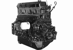
It is part 883278R5 for $4015.20 PLUS a $1000 Core Fee and a $175 Crate deposit fee.
The reman comes with a Core Worksheet and return instructions.
Only good blocks that turn with a good crank and head will qualify
for complete core credit.
Prices are subject to change!
To order parts, Email
Safety
Boats can explode. Moving parts can rip off your fingers. Hot exhaust can burn you to the bone and props can slice you up. One spark near a battery can cause an explosion. You can never be too careful. Remove the battery from the boat before working with fuel. Always disconnect the batteries negative terminal first. Clean up any spilt fuel and let ALL of the fumes dissipate before installing the battery and starting the motor. Pulleys and Belts can grab your clothes and hair. Don't wear loose clothing and keep your hair up under a hat. Always wear safety glasses. Be smart.